Building a Nixie Watch
I always liked Woz’s nixie watch, and once you see the glow of those tiny USSR digits in real life you will love them too. But all watches I found on the Internet were overpriced or lacked the features I was looking for. I also wanted to be able to program it for my own needs. So I decided to build my own watch.
As a starting point for my own watch I looked at Woz’s nixie watch, which is made by David Forbes from cathodecorner.com. He also published a technical description and schematics for his watch, which is really nice.
I used the high voltage parts of David Forbes’s design for my watch. I am only doing this for a hobby, so my PCB design and layout skills are not the best. Here’s the schematics and layout of PCBs I’ve ordered from JLCPCB:


The design has some flaws (see below), so I won’t publish it. If you are really need them, just contact me. Next I will talk about some of the interesting things about my design.
Miniature Transformer
First thing I done when I got the PCBs was to try out the HV section. I temporarily enabled the LT1308B chip by shorting its SHUTDOWN pin (active low) to Vcc. It worked at the first try. Here you can see the first light moment:
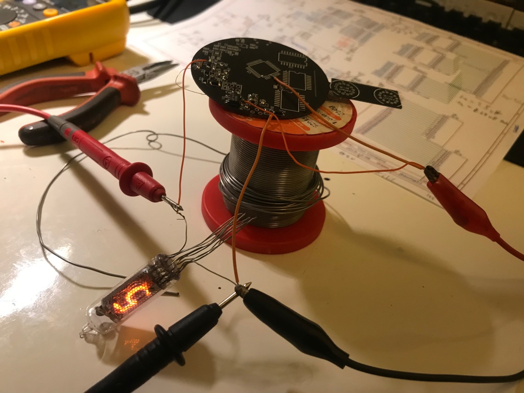
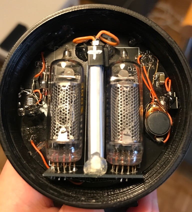
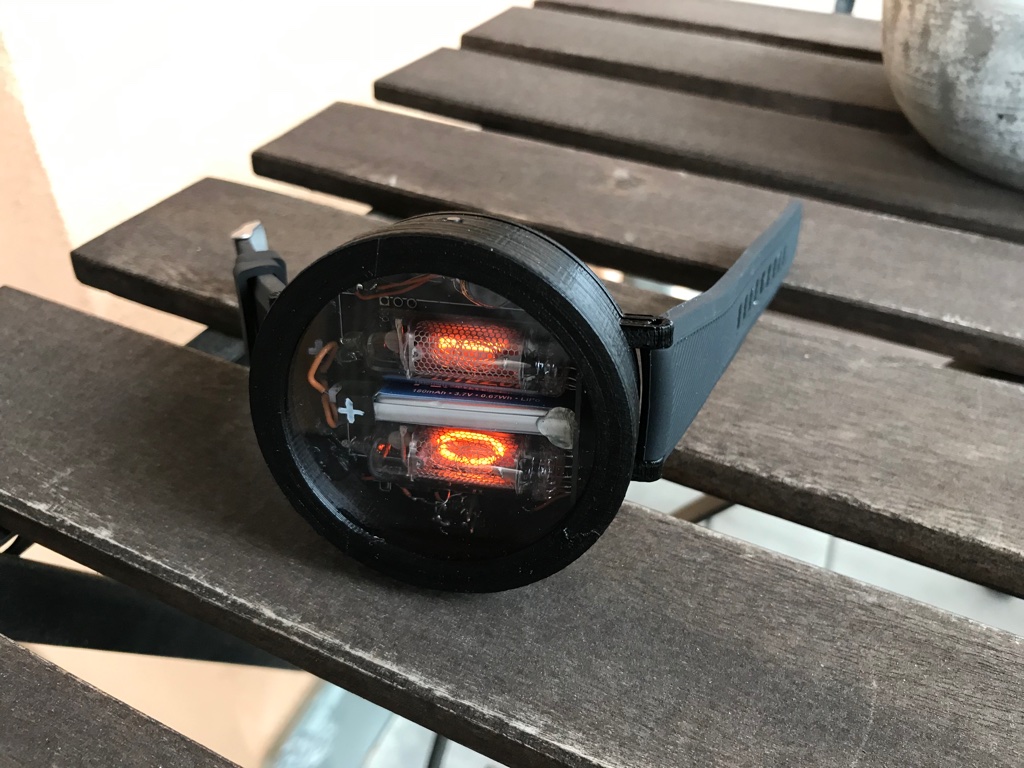
The original design from David Forbes used a Midcom 31105R transformer to step-up the battery voltage, however, I couldn’t order it anywhere. So I created my own by trying some designs. I ended up with using the inductor Fastron PISM-1R5M-04 with 1.5 µH and adding about 50 windings of 0.2 mm enameled wire. You can see the final transformer on right in this picture:
Tilt Sensor
Initially I planned to use the ADXL335 accelerometer to detect tilting motion. However, it only allows an input voltage of up to 3.6 V, so I would need to hack in a low dropout voltage regular with very low quiescent current. Furthermore, detection of a tilt motion isn’t that simple. The microcontroller has to measure the ADXL335’s analog output and guess if there was tilting.
But then I had an idea. Years ago, I bought mercury tilt switch sensors. When the bead of mercury is at a certain position, it closes the circuit. It’s easy to measure this digital signal and it also fits the theme of nixie watches very well. They are easier to solder in (compared to LFCSPs), cheaper, have no specific input voltage range, low current requirements and are way less complex to interface (accelerometer ICs usually use analog or I2C).
You can see the mercury switch in the previous picture on the left side of the left nixie tube.
RTC Code
I initially started with the code of Echtzeituhr mit Uhrenquarz from mikrocontroller.net. I ported the code to the ATmega16A. It uses a 32.768 kHz crystal and gives me a “callback” every 7.8 ms and every second.
One mistake I made was to use XTAL1 and XTAL2 for the crystal, however, you have to use TOSC1 and TOSC2. This issue is cause by the fact that on the ATmega88 (used in Echtzeituhr mit Uhrenquarz) the pins are the same, but on the ATmega16A they are not. So I had to hack in a quartz crystal at the correct pins and change the pins for the digits 6 and 7 of the left nixie tube.
For the time code I used the avr-libc’s time library, which works till the year 2136. It features support for daylight saving functions and time zones. The user interface of my watch lets you disable DST, set it to a EU or US profile and set the time zone (currently only in one hour increments).
User Interface
The UI is based on only one button. It’s inspired by the Macbook Wheel 😅:
Everything is just a few hundred clicks away.
So the basic idea was to use a short press to advance the current number and a long press to accept the setting. And the watch walks you through each setting (daylight saving time options, time zone in hours, year, month, day, hour, minute) and outputs the stored setting after you accept it.
3D Printed Enclosure
For the watch band I used a 22 mm black one from AliExpress. I designed the enclosure using Fusion 360 with a screwable lid. It works by using the tread tool and adding additional clearing to the threading. I got the idea from this video.
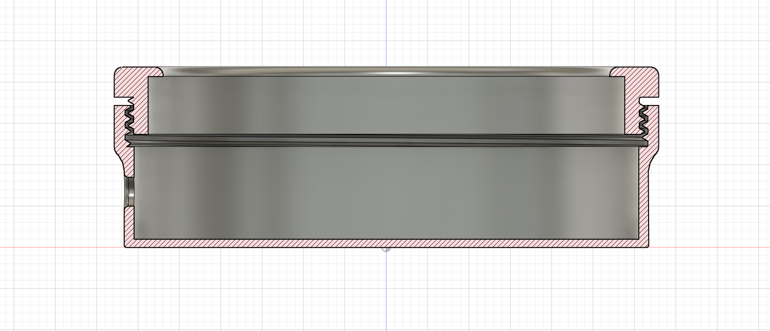
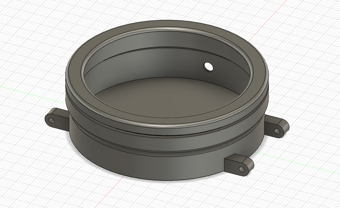
The lid has also space for a watch glass. For this project I used 2 mm polystyrene, which I “dremeled” into the right shape. This was easier than I initially thought, however, you must be very careful not to damage anything inside the final shape.
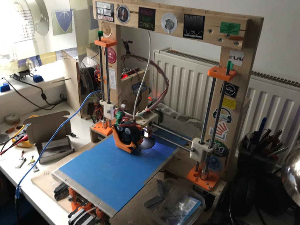
Here you can see my DIY 3D printer printing the watch enclosure and the final watch:
Final Current Measurement
The watch needs about 25 µA when the nixie tubes are off and about 200 mA when on. Of course, these numbers depend on the input voltage, aka. the current charge of the LiPo battery. This should give me about 300 days of display-off-time or (I guess) 1000 short time appearances (tilt motion activated) with the 180 mAh battery.
That’s basically it. I may do another revision. Here are some things I have to improve:
- Ditch the accelerometer, replace it with solder pads/headers for a mercury tilt switch
- Fix the button footprint (holes are wrong)
- Find a through hole micro USB port (USB-C?) or use the PCB manufacturer’s assembly service
- Add more spacing to the holes of the vertical nixie board
- Add solder pads for the 1.5 µH inductor (transformer)
- The crystal must be connected to Pins 25 and 26, no 22 pF capacitors needed
- Higher LED resistor value, 1 k is still too bright
- Use assembly service for as many parts as possible (saves a lot of time)